How to control dc motor with encoder:
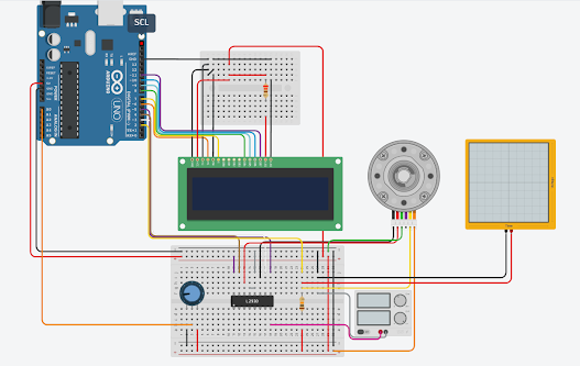
Arduino DC Motor Speed Control with Encoder- I have been using different types of stepper motors, Servo motors, and DC Motors for quite a long time in different intermediate and advanced level projects. DC motors are more frequently used than Stepper Motors and Servo Motors. If you have watched my videos and read my articles then you should know DC motors are quite different from Stepper Motors and servo Motors. These three types of motors have a different construction. The stepper motors and servo motors are designed in a way that we can control their position. We can control the steps in the forward and reverse directions. Servos can move from 0 to 180 degrees, so you can move to any position between 0 and 180. Likewise, in stepper motors, you can control the steps precisely and this is the reason stepper motors are used in CNC machines, 3d printers, etc. On the other hand, when a dc motor is powered up it immediately starts rotating, it continuously rotates, you can’t exactly control its position until you use a specific technique. You can’t 100% control a DC motor like Stepper motor and Servo, but if you add an encoder it can really change the whole game. With an encoder being added, you can keep track of the motor revolutions, the amount of distance it has covered, and this way you can make a nice feedback system that can be used to control the DC motor. Then you can stop the DC motor at the position where you want it to stop. The control of a DC motor using an encoder is not that simple, you just simply can’t start by adding an encoder with the DC Motor and start controlling the DC motor, to use an encoder you will need a controller, the controller will read the encoder and then will accordingly control the DC motor as per the pre-defined instructions written by the programmer. for this project, you will need a microcontroller board like the Arduino Uno or Arduino Nano, or Arduino Mega, or Arduino pro mini, etc. I know beginners are more comfortable with Arduino Uno, Arduino mega, and Arduino Nano, so I will start with the Arduino Uno, the same connections and programs you can also try on Arduino Nano and Arduino Mega. To get started, you will need Arduino Uno, a Motor driver, a DC Motor, and of course an Encoder. To read the Encoder, we will connect the encoder output pins with Arduino’s pins 2 and 3 which are the interrupt pins. The power wires of the encoder will be connected with the Arduino’s 5V and GND. To keep things simpler, I will start with the simple example code in which I will use pins 2 and 3 as the normal digital pins, we won’t activate the interrupts and then in the second example code, we will use the interrupts. Without any further delay, let’s get started!!!
ARDUINO CODE BELOW
#include<LiquidCrystal.h> //insere a biblioteca Liquid Crystal
LiquidCrystal lsd(6, 7, 8, 9, 10, 11); //define o objeto lsd com as funções da biblioteca Liquid Crystal e suas entradas
#define M1 4 //define a porta de uma entrada do motor
#define M2 3 //define a outra porta da entrada do motor
#define Control 5 //define a saída que controlará a velocidade do motor
#define Pot A0 //define a entrada do potenciometro
#define Encoder 2 //define a entrada dos pulsos que o motor envia
int vel; //cria a variável que dará o valor da velocidade
volatile float ripple; //define a variável que contará a quantidade de pulsos
unsigned long tempo, //define a variável que receberá o valor de millis()
TheWorld = 1000; //determina o tempo que ocorrerá a contagem
float RPM, //define a variável que receberá o valor do rpm
ppv = 611, //define a quantidade de pulsos por volta
voltas = 0; //define a variável que receberá a quantidade de voltas
void hamon() { //cria a função que contará os pulsos
ripple++; //incrementa 1 na variável ripple
}
void setup() //função principal que ocorre apenas uma vez
{
lsd.begin(16, 2); //incia o lcd informando que é do tipo 16x2
pinMode(M1, OUTPUT); //define uma entrada do motor como saída
pinMode(M2, OUTPUT); //define a outra entrada do motor como saída
pinMode(Control, OUTPUT); //define a porta que controlará a velocidade como saída
pinMode(Encoder, INPUT); //define que a porta que receberá os pulsos será de entrada
pinMode(Pot, INPUT); //define que a porta do potenciometro será de entrada
attachInterrupt(0, hamon, RISING); //define a interrupção na porta 2, na função hamon e na subida do pulso
tempo = 0; //inicia o contador para o millis()
lsd.setCursor(0, 0); //insiro o cursor na coluna 0 e linha 0
lsd.print("RPM: loading..."); //escrevo a mensagem no lcd
lsd.setCursor(0, 1); //insiro o cursor na coluna 0 e linha 1
lsd.print("Voltas: 0.00"); //escrevo a mensagem no lcd
}
void loop()//função principal que acontece repetidas vezes
{
vel = map(analogRead(Pot), 0, 1023, 0, 255); //mapeio o valor recebido pelo potenciometro em 10 bits para um valor pwm de 8 bits
analogWrite(Control, vel); //escrevo na porta de controle a velocidade do motor dependendo do potenciometro
digitalWrite(M1, 1); //defino uma saída do motor como HIGH
digitalWrite(M2, 0); //defino a outra saída como LOW
if (millis() - tempo > TheWorld) { //só entra na condição a cada 1 segundo
noInterrupts(); //interrompo as interrupções
RPM = (ripple / ppv) * 60; //calculo o valor do RPM
voltas = (voltas + (ripple / ppv)); //calculo o valor das voltas
lsd.setCursor(0, 0); //insiro o cursor na coluna 0 e linha 0
lsd.print("RPM: "); //escrevo a mensagem no lcd
lsd.print(RPM, 1); //insiro o valor do RPM no lcd com uma casa decimal
lsd.print(" "); //espaço em branco para apagar mensagens posteriores
lsd.setCursor(0, 1); //insiro o cursor na coluna 0 e linha 1
lsd.print("Voltas: "); //escrevo a mensagem no lcd
lsd.print(voltas); //insiro o valor das voltas no lcd
ripple = 0; //reinicio a contagem de pulsos para que contabilize a cada segundo
tempo = millis(); //reinicio o "cronometro" para que ele entre na condição novamente daqui a 1s
interrupts(); //retorno com as interrupções
}
}
/////////////////////////////////////////////////////////////////////////////////ARDUINO CODE IS END