Circuits Diagram Click here
Circuits Diagram Click here

Circuits Diagram Click here

BOM Click here

Circuits Diagram Click here
Arduino Circuits Code Click here
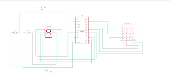
This is a simple project that shows you how to control a 7 Segment Display with a Numeric Keypad! Whatever number you press on the keypad will appear on the Seven Segment Display!
Making ItThe schematic is down below. It should be pretty easy. You need to use a 3x4 matrix keypad so you have enough pins.


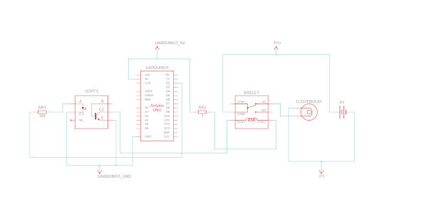
Ambulance Siren using Arduino


o get started, let’s consider the example of an Arduino microcontroller connected to the computer’s USB port (though it works with many other microcontroller boards as well). We’ll elaborate on the finer points of powering NeoPixels later, but in general you’ll usually be using a 5V DC power supply (e.g. “wall wart”) or — for wearable projects — a 3.7 Volt lithium-polymer battery.
Identify the “input” end of your NeoPixel strip, pixel(s) or other device. On some, there will be a solder pad labeled “DIN” or “DI” (data input). Others will have an arrow showing the direction that data moves. The data input can originate from any digital pin on the Arduino, but all the example code is set up for digital pin 6 by default. The NeoPixel shield comes wired this way.
Some NeoPixel strips have extra wires so they can connect to both a microcontroller and power source, but these will always correspond to one of the same three inputs: +5V, ground or data. If not using the extra wires, you can clip off any exposed tips and/or insulate with some heat-shrink tube.
If using a Flora, Feather or other microcontroller board with an attached lithium-polymer battery: connect the +5V input on the strip to the pad labeled VBAT or BAT on the board, GND from the strip to any GND pad on the microcontroller board, and DIN to Flora pin D6. If the board doesn’t have a pin #6, you’ll need to modify the example code to change the pin number.
For other Arduino boards with a separate +5V DC power supply for the NeoPixels: connect the +5V input on the strip to the + (positive) terminal on the power supply (don’t connect to the Arduino), DIN to digital pin 6 on the Arduino, and – (minus or GND) on the strip must connect to both the minus (–) terminal on the DC supply and a GND pin on the Arduino (there are usually several — any will do).
“DOUT” or “DO” (data out) at the end of a NeoPixel chain can be left unconnected. If adding more pixels later, data-out from one chain connects to data-in of the next.
The 144 pixel strips are so tightly packed, there’s no room for labels other than –, + and the data direction arrows. Data is the third, un-labeled pad.


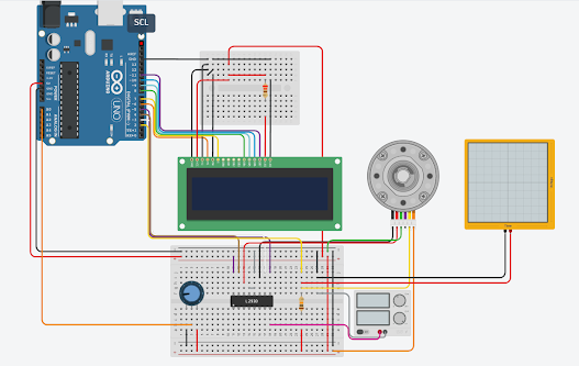
Digital Temperature and LCD Arduino
In this project we are going to use a temperature sensor in order to read its value and displaying on a LCD screen.
We connected two potentiometer in order to adjust LCD backlight and contrast as well.
After sketch loading completed, your board will display current temperature, but only after computing an average of 100 samples read from temperature sensor. This to avoid crazy reading data every cycle.
Hardware components required:
Software requirements:
The LM35 is a good performance temperature sensor at a low price. It has a working range from -55ºC to 150ªC. Its output is analog and linear type with a slope of 10mV / ºC. The sensor is factory calibrated to an accuracy of 0.5ºC.
It is a very popular sensor for its easy use and varied applications. It does not need any additional circuit to be used. It is powered directly from a 5V source and delivers an analog output between 0V to 1.5V. This analog voltage can be read by the ADC from a microcontroller like PIC or Arduino. Among its applications we can find thermometers, thermostats, monitoring systems and more.
In above picture we connected lm35 temperature sensor to Arduino as first pin for power source is connected to 5V on the Arduino and the second pin is connected to A2 of Arduino analogue pin and the third one is connected to GND of Arduino UNO.
We connected 16 X 2 LCD display with the help of I2C adapter, all the connection pins are given in the image which has two pins for power and ground and another two for SDA and SCL.
We connected two small Red and Green 5mm LED light to digital pins 6 and 7 and we connected 100 ohms resistors along the ground of LED lights.
After uploading the code you will notice the live temperature for the sensor is displayed on the 16 X 2 LCD display. If the temperature raised above 60 the red LED will light up and if the temperature is below 60 Green LED will light up. You can adjust the threshold temperature in the above code to make the lights change at what temperature you want.

YouTube: https://www.youtube.com/channel/UCcwnTKWxSlkv_iarGQ_zbPg/featured
Instagram:
https://www.instagram.com/?hl=en
Facebook:
https://www.facebook.com/Creative-ideas-EEE-110709481470623/?ref=pages_you_manage
How to control dc motor with encoder: Arduino DC Motor Speed Control with Encoder- I have been using different types of stepper motors, Ser...