Sunday, January 30, 2022

Temperature controlled fan using Arduino

       Temperature controlled fan using Arduino


Introduction

Temperature controlling is required in many places such as server rooms, houses, industries, etc. So this project can be very useful in understanding the basics, how you can control the temperature at your home. You can take this as a DIY project which can be used anywhere. Here the Temperature controlled fan will act to the temperature changes.

We have also written a blog on what temperature sensors are, if you are interested feel free to read that as well to understand more about these types of sensors.

We are going to do this with a DHT11 temperature and humidity sensor. It can be done in various other ways as well. With a thermistor or other sensors like a contactless temperature sensor. But thermistor usually needs contact of the surface and contactless sensors can be costly. While DHT11 is a cost-effective sensor.

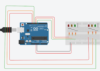
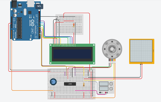
In this article, we are going to discuss making a temperature-controlled fan using Arduino. With this circuit, we will be able to change the fan speed in our home or any place according to the room temperature and also display the temperature and fan speed changes on a 16x2 LCD display. To do this we will be using an Arduino UNO Board, LCD, DHT11 sensor Module, and DC fan. Let's get started.

In the second step, the sensor's output is taken and conversion of temperature value into a suitable number in Celsius scale is done. The fan speed is controlled by using PWM signals. And last part of the system shows humidity and temperature on LCD and Fan runs.

Then we have programmed our Arduino according to the requirements. Working on this is very simple. We have generated PWM from Arduino and put it at the base terminal of the transistor. Then transistor generates voltage with respect to the PWM input.


Components required
Circuits Diagram : Click Here

BOM : Click Here

Arduino Code : Click Here

Arduino Code : Click Here

Arduino Code : Click Here

YouTube : Click Here 

YouTube: https://www.youtube.com/channel/UCcwnTKWxSlkv_iarGQ_zbPg/featured


Instagram:
https://www.instagram.com/?hl=en


Facebook:

https://www.facebook.com/Creative-ideas-EEE-110709481470623/?ref=pages_you_manage


Saturday, January 29, 2022

Arduino with PIR MOTION SENSOR

                    Arduino with PIR Motion Sensor


How PIR Motion Sensors Work

Passive Infra Red sensors can detect movement of objects that radiate IR light (like human bodies). Therefore, using these sensors to detect human movement or occupancy in security systems is very common. Initial setup and calibration of these sensors takes about 10 to 60 seconds.

The HC-SR501’s infrared imaging sensor is an efficient, inexpensive and adjustable module for detecting motion in the environment. The small size and physical design of this module allow you to easily use it in your project.

The output of PIR motion detection sensor can be connected directly to one of the Arduino (or any microcontroller) digital pins. If any motion is detected by the sensor, this pin value will be set to “1”. The two potentiometers on the board allow you to adjust the sensitivity and delay time after detecting a movement.


PIR modules have a passive infrared sensor that detects the occupancy and movement from the infrared radiated from human body. You can use this module in security systems, smart lighting systems, automation, etc. There are different PIR modules available in the market, but all of them are basically the same. They all have at least a Vcc pin, GND pin, and digital output. In some of these modules, there is a ball like a lens on the sensor that improves the viewing angle.


There is a jumper behind this module. If you move the jumper to L position, the sensor will ‘toggle’ (change state) whenever motion is detected. This is unlikely to be of much use in a practical applications. This mode is called non-triggering or Single Triggering mode.

Moving the jumper to the H position will result in the more usual sensor logic. The sensor will turn on when motion is detected and turn off a while after the last motion is detected. This sensor will reset the timer (which would otherwise turn the output off) each time motion is detected; this would be applicable, for example, for room occupancy lighting control where you don’t want the lights to blink off while the unit resets. This is called Retriggering mode. (or repeatable trigger mode).

There are also two potentiometers behind this module. By changing the SENSITIVITY potentiometer, you can reduce or increase the sensitivity of the sensor (clockwise increase), and also by changing TIME potentiometer the output delay after movement detection will be changed.

Code

You must add the library and then upload the code. If it is the first time you run an Arduino board, Just follow these steps:

  • Go to www.arduino.cc/en/Main/Software and download the software of your OS. Install the IDE software as instructed.
  • Run the Arduino IDE and clear the text editor and copy the following code in the text editor.
  • Choose the board in tools and boards, then select your Arduino Board.
  • Connect the Arduino to your PC and set the COM port in tools and port.
  • Press the Upload (Arrow sign) button.
  • You are all set!
Circuits Diagram :Click Here 

BOM  :Click Here 


Arduino Code :Click Here 


Full Video : Click Here


YouTube: https://www.youtube.com/channel/UCcwnTKWxSlkv_iarGQ_zbPg/featured


Instagram:
https://www.instagram.com/?hl=en


Facebook:

https://www.facebook.com/Creative-ideas-EEE-110709481470623/?ref=pages_you_manage


Arduino with NeoPixel

                                 Arduino with NeoPixel


Circuits Diagram Click Here


Arduino Code: Click Here

YouTube: https://www.youtube.com/channel/UCcwnTKWxSlkv_iarGQ_zbPg/featured


Instagram:
https://www.instagram.com/?hl=en


Facebook:

https://www.facebook.com/Creative-ideas-EEE-110709481470623/?ref=pages_you_manage


Thursday, January 27, 2022

Using A TMP36 Temperature Sensor With Arduino


          Creative Ideas EEE           


  The TMP36 temperature sensor is an easy way to measure temperature using an Arduino! The sensor can measure a fairly wide range of temperature (-50°C to 125°C), is fairly precise (0.1°C resolution), and is very low cost, making it a popular choice. In this tutorial we will go over the basics of hooking the TMP36 up and writing some basic code to read the analog input it is connected to.


How It Works:
Unlike a thermistor, the TMP36 does not have a temperature sensitive resistor. Instead this sensor uses the property of diodes; as a diode changes temperature the voltage changes with it at a known rate. The sensor measures the small change and outputs an analog voltage between 0 and 1.75VDC based on it. To get the temperature we just need to measure the output voltage and a little bit of math!


We are dealing with the TMP36 from Analog Devices - here is the datasheet.

First, we clarify the questions of whether a sensor can also be tested without a device. First of all: yes ;-)

Then we look at the method of how to convert the voltage into the temperature.

Apply 2.7-5.5V to the left leg via batteries or another power source. Connect the right leg to GND (2-4 AA batteries work fantastic). The writing on the sensor is facing you. The semicircular circle lies on the floor.

The voltage is measured over the middle leg: use a multimeter and connect GND with GND and use the red reading head of the multimeter to read the voltage on the middle leg.

My comfortable room temperature is apparently 0.718 volts.

You can safely touch the sensor with your fingers or hold it under a heat-emitting lamp: the voltage value changes immediately.

And how can we convert the voltage into a temperature?

If you're using a 5V Arduino, and connecting the sensor directly into an Analog pin, you can use these formulas to turn the 10-bit analog reading into a temperature:

Voltage at pin in milliVolts = (reading from ADC) * (5000/1024)This formula converts the number 0-1023 from the ADC into 0-5000mV (= 5V)


Circuits For Temperature TMP36 Click Here


BOM For Temperature TMP36 Click Here
Better understanding YouTube Click Here 


Arduino code For Temperature TMP36 Click Here


YouTube: https://www.youtube.com/channel/UCcwnTKWxSlkv_iarGQ_zbPg/featured


Instagram:
https://www.instagram.com/?hl=en


Facebook:

https://www.facebook.com/Creative-ideas-EEE-110709481470623/?ref=pages_you_manage

Tuesday, January 25, 2022

Traffic Light Controller Project Tutorial

                      Creative ideas EEE


LEDs with Arduino: everything you need to know

The first thing to know before using multiple LEDs is that it is a diode. These types of components are very particular since they only allow electricity to pass in one direction.

But what is that meaning? It is very simple and with practice, you will get used to using them. LEDs have one longer pin than another, that pin is known as the anode (the positive pole). It is where the current has to enter. The smallest pin is known as the cathode (negative pole) and this is where the current of electrons will exit.

LED well connected

With this clear, we can now connect multiple LEDs to our circuit. Now we just need to know what resistance to put. For this we must make use of Ohm’s Law. This Law is the fundamental base on which we must build our circuits.

This Law relates the three basic magnitudes of a voltage, current and resistance circuit. You must know and memorize the formulas that help us calculate one quantity in relation to the others. There is a circle that helps you easily remember this relationship. Covering the magnitude you want to calculate tells you how to do it based on the other two magnitudes.

A close up of a sign

Description automatically generated

With this formula we can calculate any magnitude. In principle, we need to know two of the magnitudes to calculate the third. In the example of the intelligent traffic light with multiple LEDs and buttons, we will have to calculate it only once. Let’s see how to do it. First, take a look at this circuit:

A circuit board

Description automatically generated

In a series circuit like the one in the example, it does not matter if you put the resistance before or after. Applying Ohm’s Law, you get the same value. At no time does this Law tell us the position of the components. This also applies to multiple LEDs.

It is a very simple circuit, an LED and a parallel resistance. But how do we calculate the value of resistance? We just have to apply Ohm’s Law. We know the voltage, 5 V, is supplied by the digital pins. The intensity can be obtained from the technical characteristics sheet of the Arduino itself as


Building an Arduino traffic light controller helps you develop basic coding skills! We get you started.


The Arduino traffic light is a fun little project that you can build in under an hour. Here's how to build your own using an Arduino, and how to change the circuit for an advanced variation.


Circuits Diagram:    Click Here
BOM Arduino with 7 segment  Code Click Here
       

YouTube Channel for more information : 

What You Need to Build an Arduino Traffic Light Controller

BOM:   Click Here

BOM  Arduino with 7 segment  Code Click Here


Arduino Code :    Click Here
Arduino with 7 segment  Code Click Here


Arduino Code:   Click Here

Arduino with 7 segment  Code Click Here

YouTube: https://www.youtube.com/channel/UCcwnTKWxSlkv_iarGQ_zbPg/featured


Instagram:
https://www.instagram.com/?hl=en


Facebook:

https://www.facebook.com/Creative-ideas-EEE-110709481470623/?ref=pages_you_manage


Saturday, January 22, 2022

Easy way to Make the AND logic by help of Arduino


                Creative Ideas EEE


What is Arduino?

Arduino is an open-source electronics platform based on easy-to-use hardware and software. Arduino boards are able to read inputs - light on a sensor, a finger on a button, or a Twitter message - and turn it into an output - activating a motor, turning on an LED, publishing something online.

Which language is used in Arduino?

The Arduino IDE supports the languages C and C++ using special rules of code structuring. The Arduino IDE supplies a software library from the Wiring project, which provides many common input and output procedures.

What is the function of Arduino Uno?


Arduino UNO is a low-cost, flexible, and easy-to-use programmable open-source microcontroller board that can be integrated into a variety of electronic projects. This board can be interfaced with other Arduino boards, Arduino shields, Raspberry Pi boards and can control relays, LEDs, servos, and motors as an output


Explore a step-by-step guide to setup the environment of Arduino programming

  1. Download & install the Arduino environment (IDE) 
  2. Launch the Arduino IDE. 
  3. If needed, install the drivers. 
  4. Connect the board to your computer via the USB cable.
  5. Select your board. 
  6. Select your serial port. 
  7. Open the blink example.
  8. Upload the program.

Arduino Playlist: Arduino List

Electronics Circuits : Click Here

LabVIEW Programming :  Click Here


Basic And Derived Logic Gates

AND, OR, NOT, NAND, NOR are the basic logic gates. Basic gate combines together to form Derived logic gates like XOR, XNOR etc.

What is Logic AND Gate

AND Gate is a basic logic gate which provides High-State “1” once all of the inputs to the AND Gate are High-State”1”. If any of the input is Low-State ”0”, than its output is Low-State ”0” .It is also referred to as arithmetic multiply operation.


AND Gate Logic in Arduino Click Here


AND Gate Logic Symbol, Boolean Expression & Truth Table

AND Gate Symbol

There are 3 types of symbols used for AND gate all over the world

American National Standards Institute (ANSI)/ MILITARY


International Electrotechnical Commission (IEC)/EUROPEAN


Boolean Expression

C = A.or C = A & B

Truth Table

A mathematical table used to specify input to output logic combination of a digital circuit is known as a truth table, the truth table of AND Gate is given below.

AND Gate Logic Flow Schematic Diagram


Construction and Working Mechanism of AND Gate:

AND Gate using Resistor-Diode Logic(RDL)

In Resistor-Diode Logic (RDL), the diode is used as a switch. In AND Gate, diodes are placed in such configuration when any of the two input is logic-Low “0”, the corresponding diode will become forward bias and logic-Low”0” will flow through output as there is no resistance in its path. When both inputs are logic-High”1” diodes will be reversed biased, Hence Vsupply (Logic High state) will be routed to output C as “1”.

NOTE: There is always diode forward voltage drop of approximately 0.7 volts in the case of silicon and 0.3 volts in the case of the germanium diode.


AND Gate using Resistor-Transistor Logic (RTL)

In Resistor-Transistor Logic (RTL), the main switching unit is the transistor. In the figure given below, there are 2 NPN transistors connected in series that switches on with logic level high ”1”, when both of the transistors are turned on, Vcc”1” will flow through output. There is a pull-down resistor connected to the output, Therefore there will be always Logic-Low”0” at the output unless both of the transistors are switched on.

NOTERTL logic limitation or disadvantage is that it has high power dissipation due to current flow in base resistors and collector resistors when the BJT’s are switched on.


Arduino And AND Gate Circuits Diagram 

Circuits : Click Here

BOM of AND Gate with Arduino 
BOM : Click Here

Arduino Code : Click Here to Download the Code

Arduino Code : Click Here to Download the Code


YouTube: https://www.youtube.com/channel/UCcwnTKWxSlkv_iarGQ_zbPg/featured


Instagram:
https://www.instagram.com/?hl=en


Facebook:

https://www.facebook.com/Creative-ideas-EEE-110709481470623/?ref=pages_you_manage


dc motor with encoder arduino

How to control dc motor with encoder: Arduino DC Motor Speed Control with Encoder-  I have been using different types of stepper motors, Ser...