Creative Ideas EEE

What is Arduino?
Arduino is an open-source electronics platform based on easy-to-use hardware and
software. Arduino boards are able to read inputs - light
on a sensor, a finger on a button, or a Twitter message - and turn it into an
output - activating a motor, turning on an LED, publishing something online.
Which language is
used in Arduino?
The Arduino IDE
supports the languages C and C++ using special rules of code
structuring. The Arduino IDE supplies a software library from the Wiring
project, which provides many common input and output procedures.
What is the function of Arduino Uno?


Arduino UNO is a
low-cost, flexible, and easy-to-use programmable open-source microcontroller
board that can be integrated into a variety of electronic projects. This board
can be interfaced with other Arduino boards, Arduino shields, Raspberry Pi
boards and can control relays, LEDs, servos, and motors as an output
Explore a
step-by-step guide to setup the environment of Arduino programming
- Download & install the
Arduino environment (IDE)
- Launch the Arduino IDE.
- If needed, install the
drivers.
- Connect the board to your
computer via the USB cable.
- Select your board.
- Select your serial port.
- Open the blink example.
- Upload the program.
Electronics Circuits : Click Here
LabVIEW Programming : Click Here
Basic And Derived Logic Gates
AND, OR, NOT, NAND, NOR are the basic logic gates. Basic gate combines together to form Derived logic gates like XOR, XNOR etc.
What is Logic AND Gate
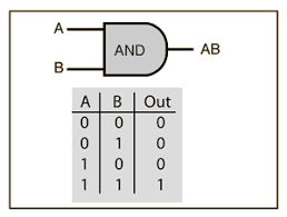
AND Gate is a basic logic gate which provides High-State “1” once all of the inputs to the AND Gate are High-State”1”. If any of the input is Low-State ”0”, than its output is Low-State ”0” .It is also referred to as arithmetic multiply operation.

AND Gate Logic in Arduino Click Here
AND Gate Logic Symbol, Boolean Expression & Truth Table
AND Gate Symbol
There are 3 types of symbols used for AND gate all over the world
American National Standards Institute (ANSI)/ MILITARY
International Electrotechnical Commission (IEC)/EUROPEAN
Boolean Expression
C = A.B or C = A & B
Truth Table
A mathematical table used to specify input to output logic combination of a digital circuit is known as a truth table, the truth table of AND Gate is given below.
AND Gate Logic Flow Schematic Diagram
Construction and Working Mechanism of AND Gate:
AND Gate using Resistor-Diode Logic(RDL)
In Resistor-Diode Logic (RDL), the diode is used as a switch. In AND Gate, diodes are placed in such configuration when any of the two input is logic-Low “0”, the corresponding diode will become forward bias and logic-Low”0” will flow through output as there is no resistance in its path. When both inputs are logic-High”1” diodes will be reversed biased, Hence Vsupply (Logic High state) will be routed to output C as “1”.
NOTE: There is always diode forward voltage drop of approximately 0.7 volts in the case of silicon and 0.3 volts in the case of the germanium diode.
AND Gate using Resistor-Transistor Logic (RTL)
In Resistor-Transistor Logic (RTL), the main switching unit is the transistor. In the figure given below, there are 2 NPN transistors connected in series that switches on with logic level high ”1”, when both of the transistors are turned on, Vcc”1” will flow through output. There is a pull-down resistor connected to the output, Therefore there will be always Logic-Low”0” at the output unless both of the transistors are switched on.
NOTE: RTL logic limitation or disadvantage is that it has high power dissipation due to current flow in base resistors and collector resistors when the BJT’s are switched on.


YouTube: https://www.youtube.com/channel/UCcwnTKWxSlkv_iarGQ_zbPg/featured
Instagram:
https://www.instagram.com/?hl=en
Facebook:
https://www.facebook.com/Creative-ideas-EEE-110709481470623/?ref=pages_you_manage


Your arduino code was very helpful for my project.your arduino code very easy to understand and download the code from your site.Thank you so much
ReplyDelete